

Please Read Carefully-
Some vehicles may require rear camera relocation depending on the factory spare-tire setup and vehicle configuration. In most cases, the process involves removing the factory rear camera from the OEM spare-tire mount, routing the wiring through the rear gate, and securing the camera in the designated GLO-shield housing before verifying proper alignment and functionality.
For customers who plan to remove the tire cover system frequently, we strongly recommend using a separate compatible rear camera rather than repeatedly disconnecting and relocating the factory camera. This helps simplify installation, makes future removal easier, and reduces unnecessary handling of the OEM camera and wiring. Wire-harness and separate OEM camera purchase links included on this page.
The tutorials provided below are intended as general installation guidance only, and requirements may vary by vehicle, trim level, wiring configuration, and aftermarket modifications. Professional installation is recommended, and any additional cameras, extension wiring, adapters, or vehicle-specific components must be purchased separately when required. Wire Harness may vary on different vehicle models. Please make sure you find YOUR specific vehicle configuration and wire-harness.
Purchase links:

Camera Relocation:
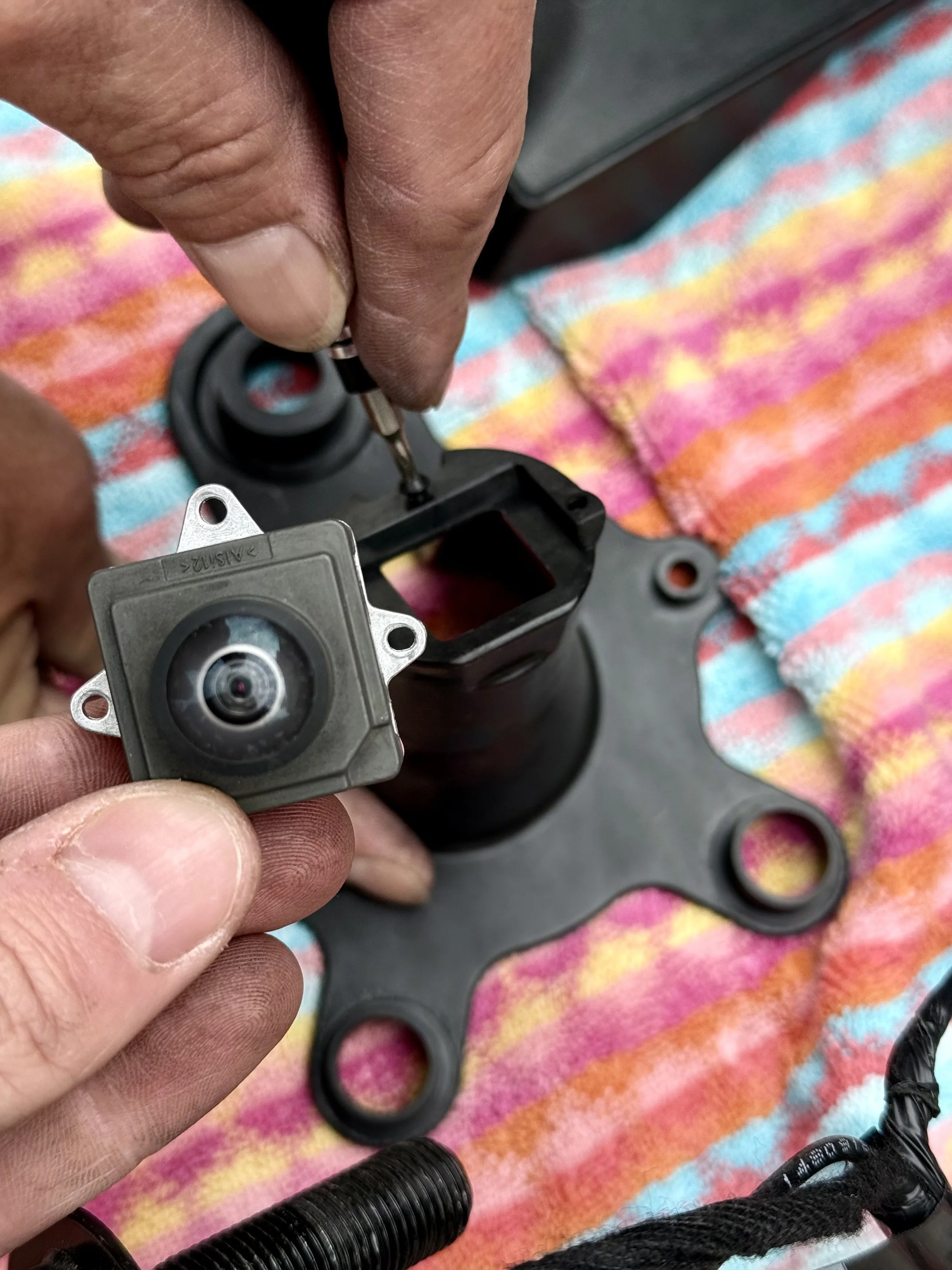
Remove:
-Remove the factory rear camera assembly from the OEM spare tire mount.
-Camera mounting systems may vary by vehicle model and trim package.
*Professional installation is recommended.
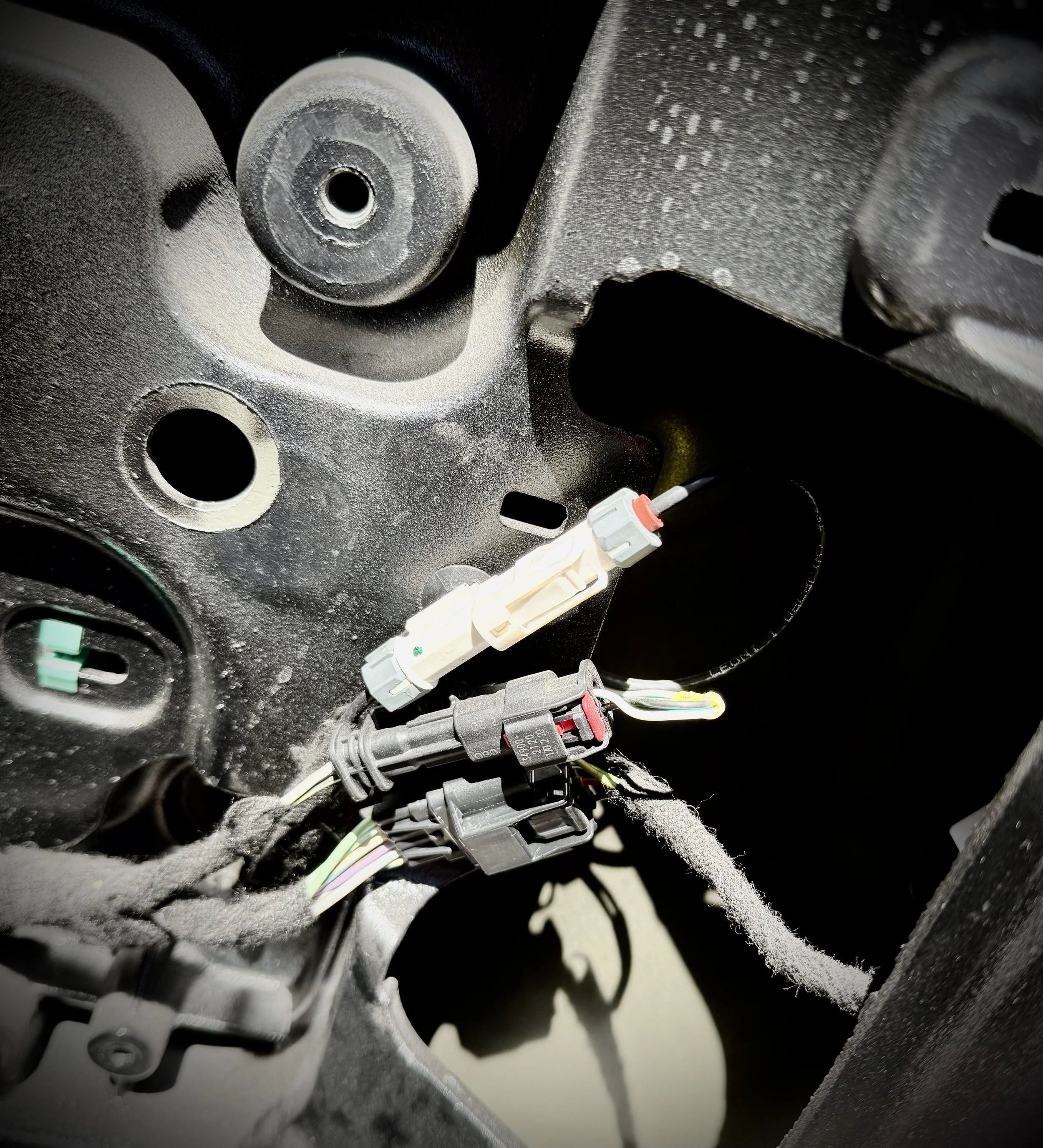
Plug:
-Route and secure the camera wiring through the rear gate using the provided camera harness location inside the GLO-shield system.
-Ensure all wiring is safely secured away from moving components
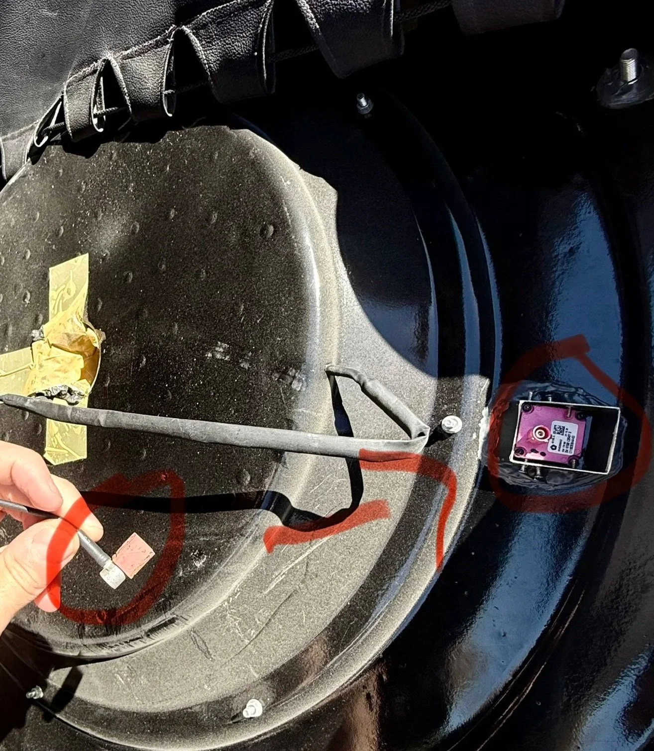
Mount & Connect:
-Mount the relocated camera into the designated rear camera housing and connect the factory wiring.
-Verify proper camera alignment and functionality before vehicle operation.
*Additional extension wiring may be required for certain vehicle configurations.
Installation Notice:
*Professional installation is recommended. GLO-shield is not responsible for vehicle damage, improper installation, camera malfunction, wiring issues, or accidents resulting from incorrect setup or use of the product. Installation requirements may vary depending on vehicle configuration and aftermarket modifications.
Wire Adapter:
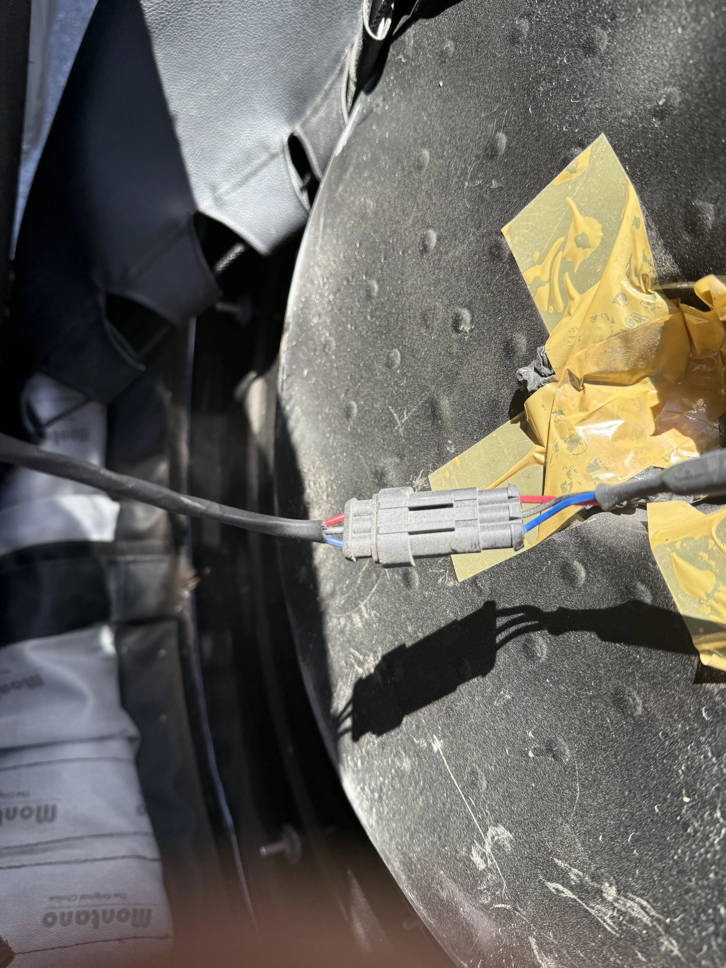
Connect:
Connect the provided power cable to the GLO-shield tire cover connection point.
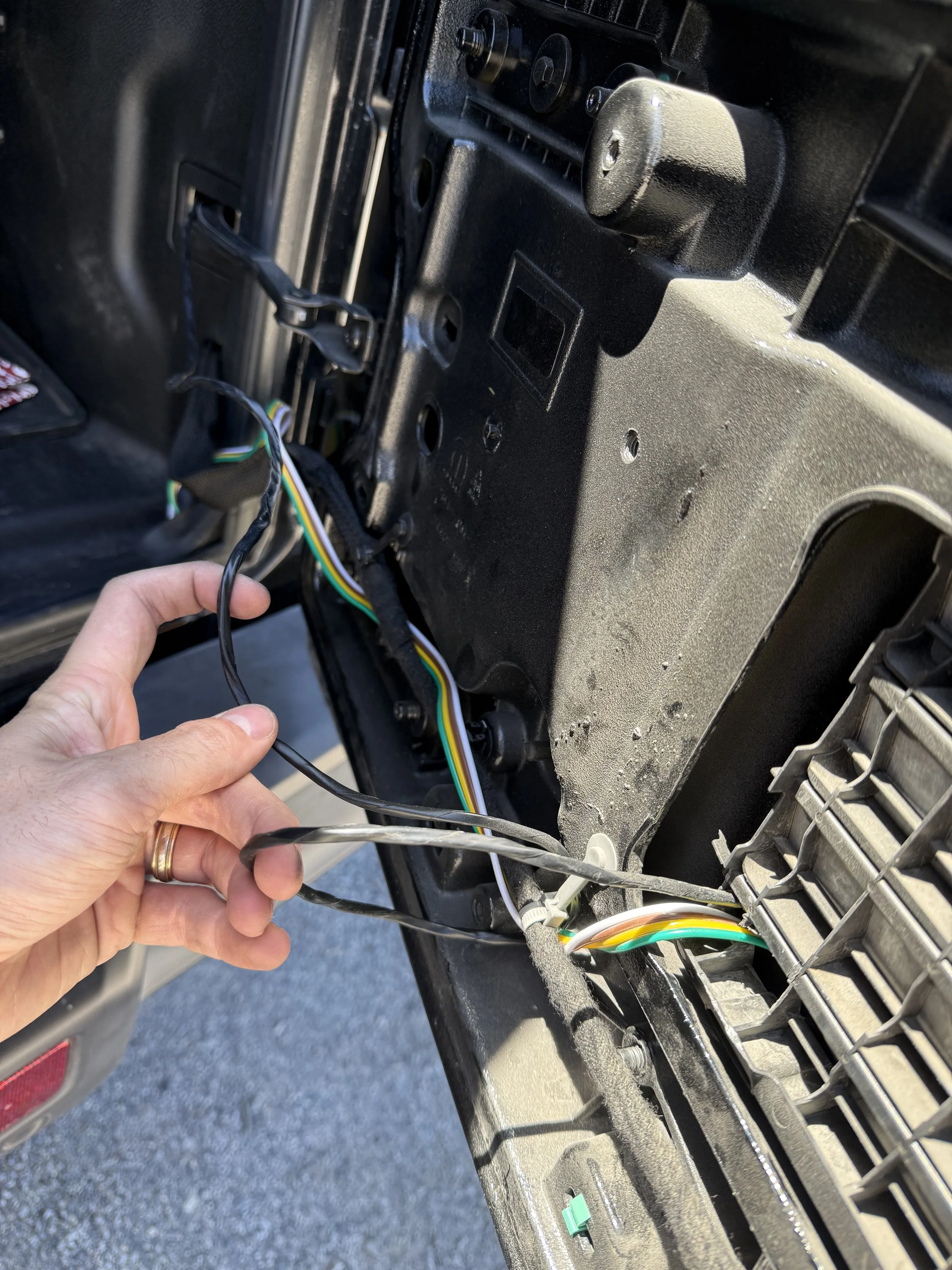
Relocate cord:
Carefully route the wiring through the rear gate area, keeping the cable away from moving parts, and sharp edges.
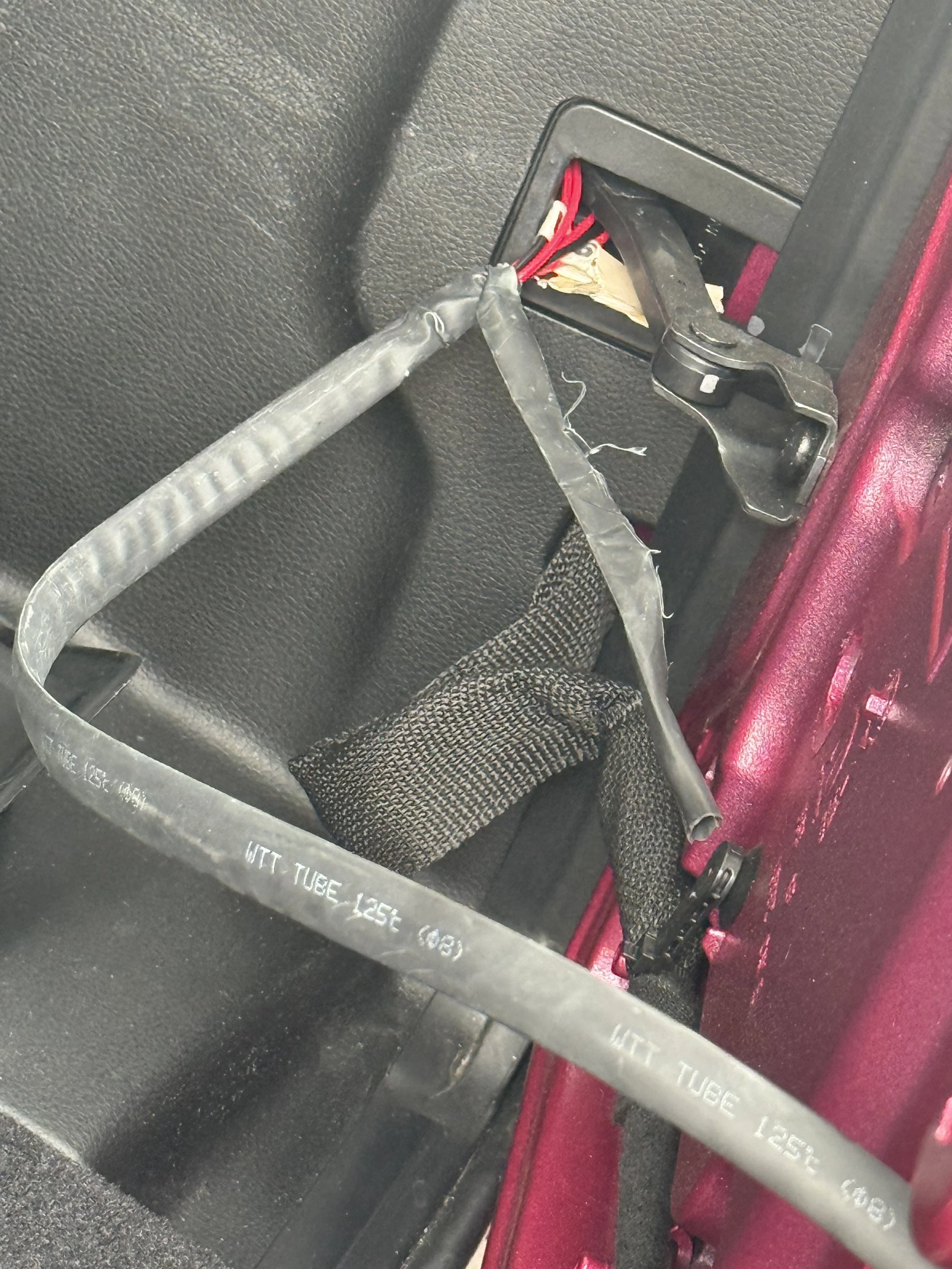
Through the Hinge:
Guide the cable through the rear gate hinge area with enough slack to allow normal opening and closing.
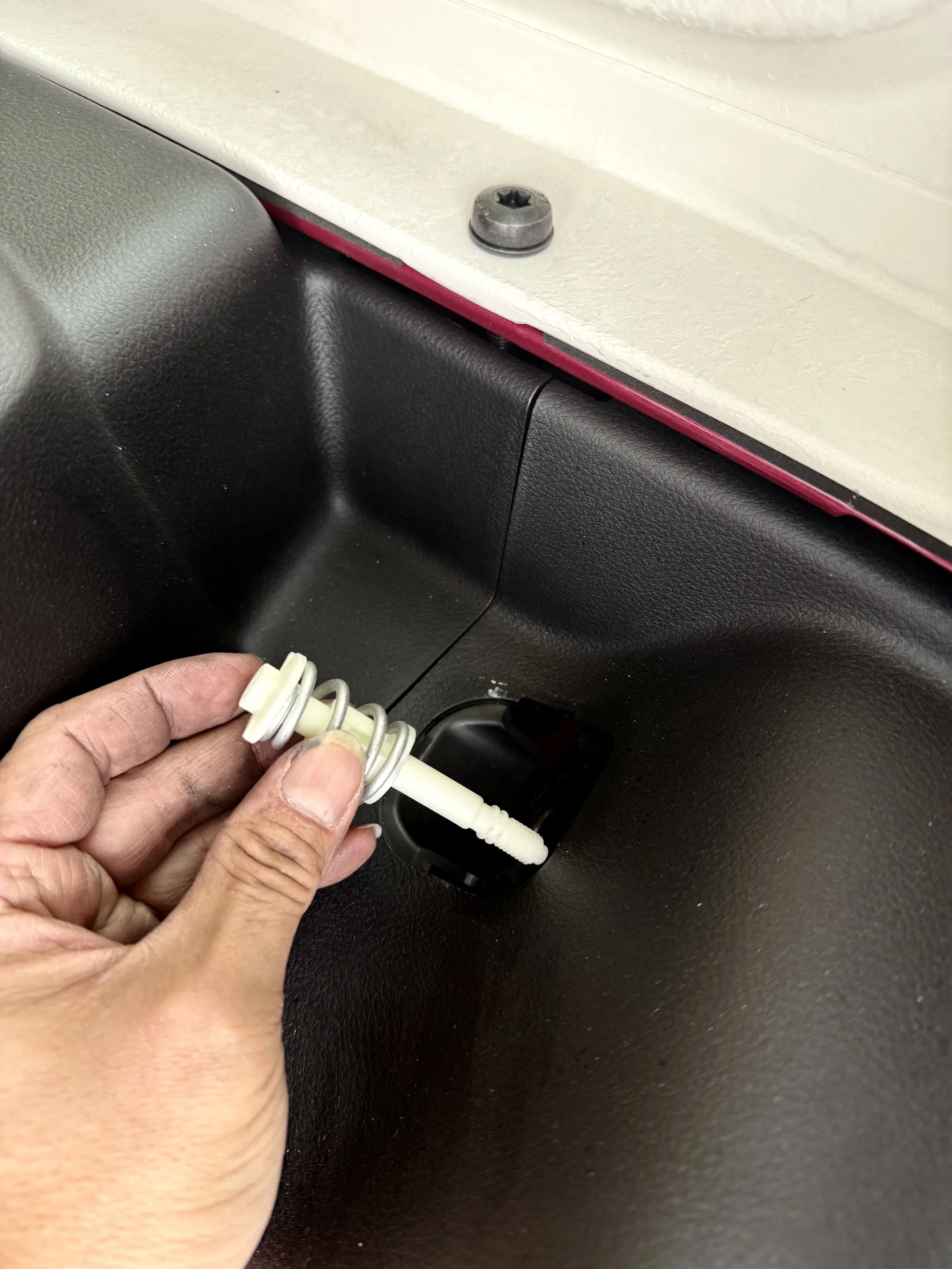
Remove Tail Light Lock:
Remove the tail light locking screw or clip to access the rear light housing.
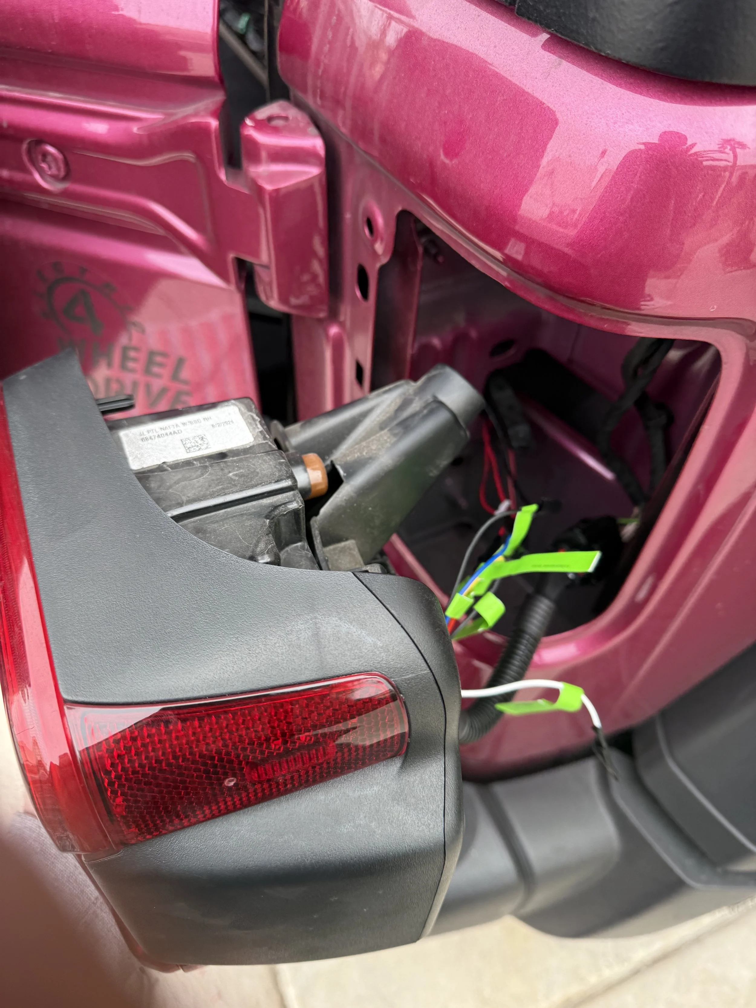
Remove Tail Light:
Carefully remove the tail light assembly to access the vehicle wiring area.
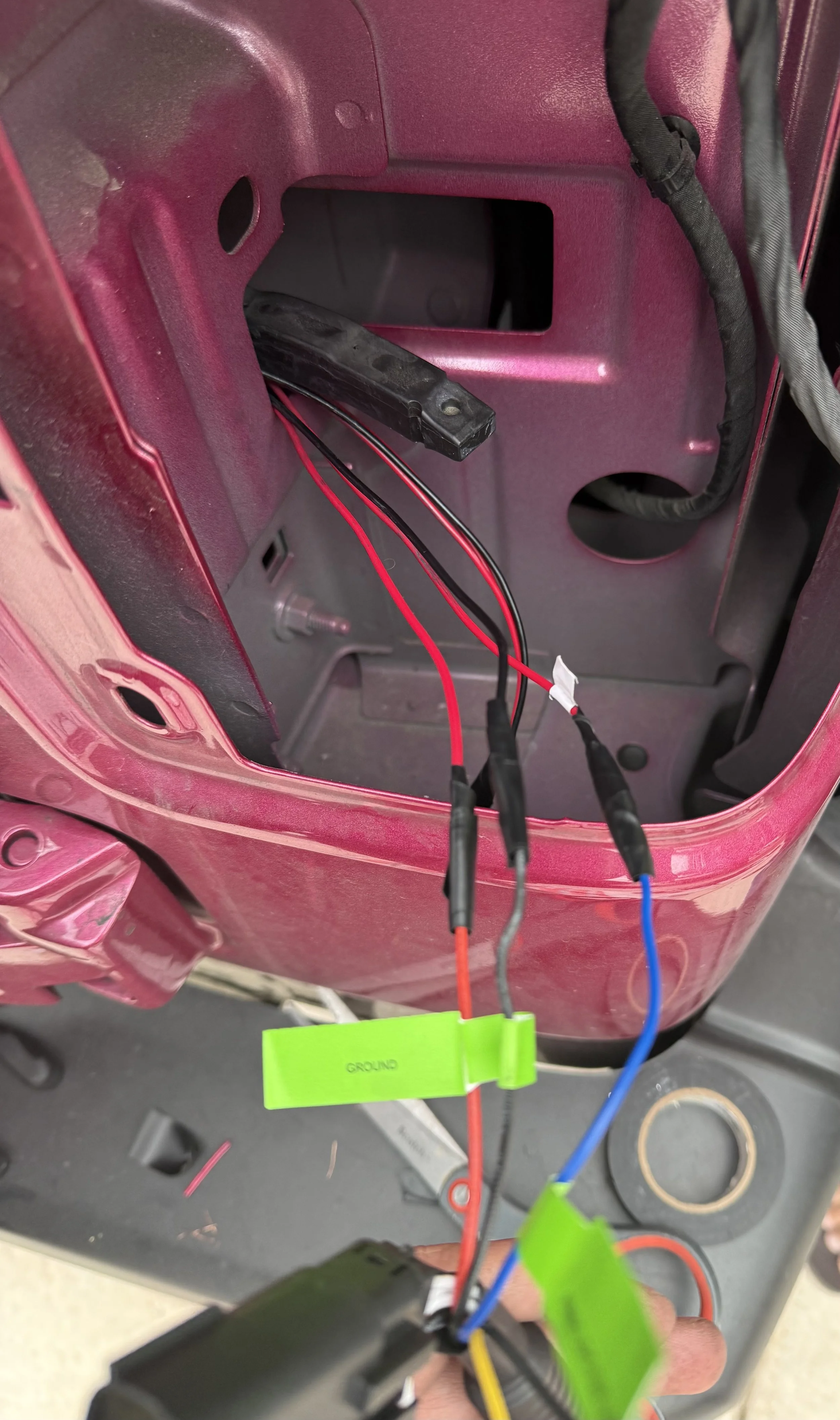
Wire Connection:
(Sold Separately)
Connect the labeled adapter wires to the appropriate vehicle wiring points.
*Professional installation is strongly recommended for this step. Incorrect wiring may cause electrical issues or product malfunction.
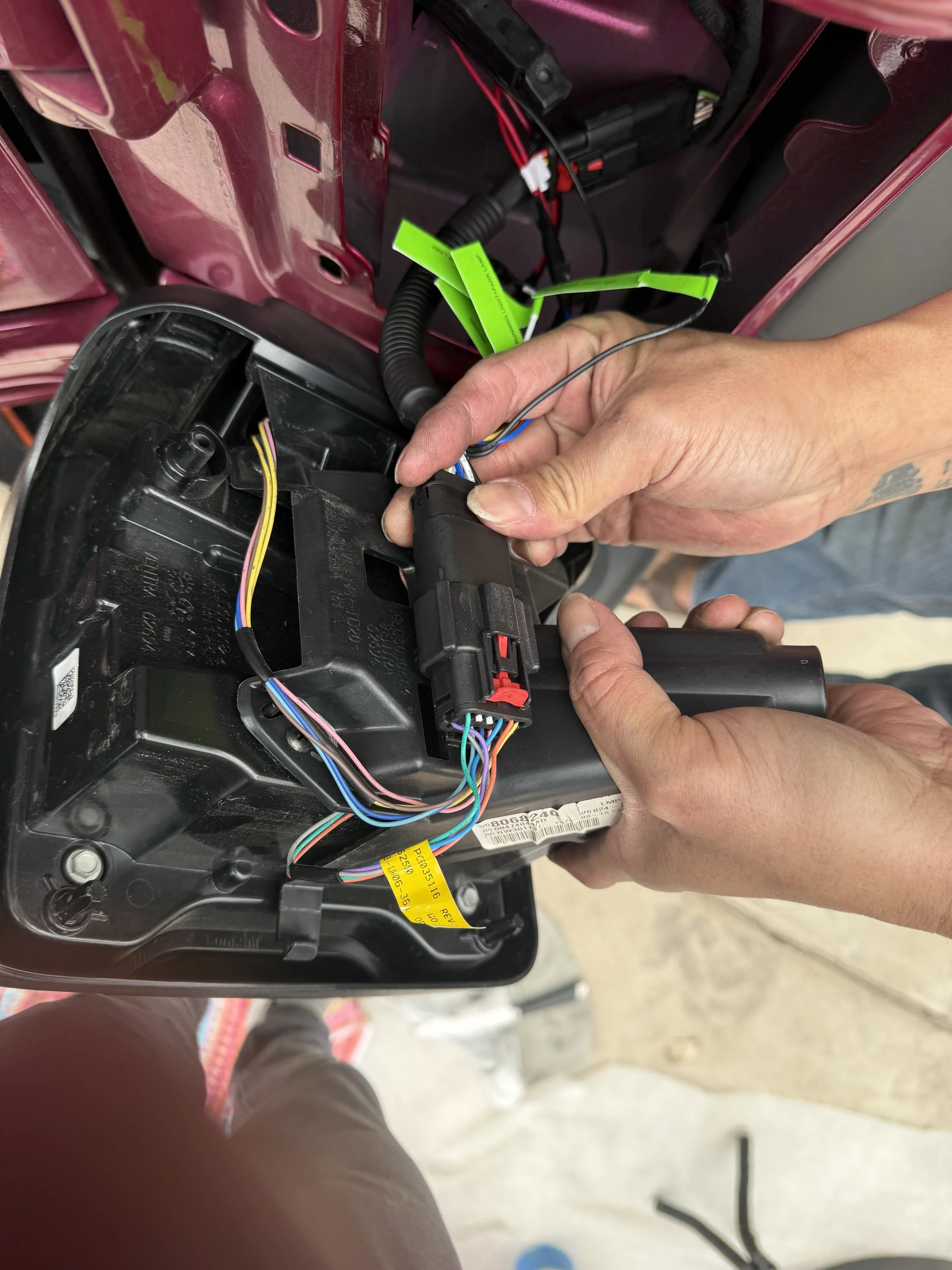
Connect Adaptor
Attach the wiring adapter securely and confirm all connections are fully seated.
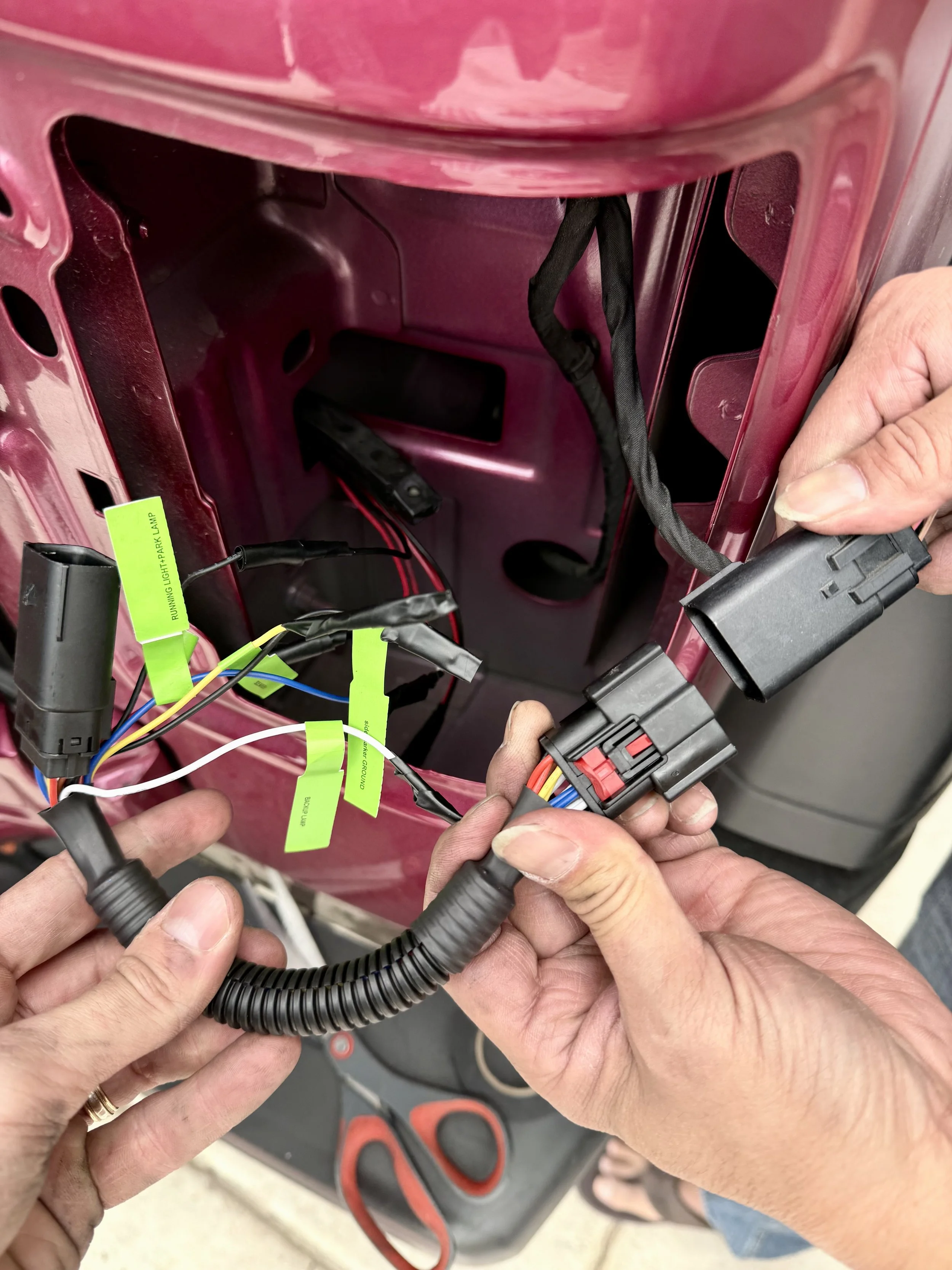
Secure Harness to Vehicle:
Secure the wiring harness to the vehicle using appropriate fasteners, keeping it clear of heat, moisture, and moving components.
Re-attach:
Reinstall the tail light assembly and confirm the GLO-shield lighting system functions properly before driving.
Installation Notice:
GLO-shield wiring adapters and lighting components may require vehicle-specific installation. Wiring locations, colors, and configurations can vary by make, model, year, trim, and aftermarket modifications. Customers are responsible for confirming compatibility and proper installation. GLO-shield is not responsible for damage, malfunction, electrical issues, or improper installation resulting from incorrect wiring or unauthorized modifications. Professional installation is recommended.